How to Install and Adjust a Brake Proportioning Valve
Date Posted:1 March 2026
A brake proportioning valve is one of the most useful, and most misunderstood, components on a race car. Get it right and you can dial in front-to-rear brake balance that holds up under both light and heavy braking. Get it wrong and you will chase a car that locks a rear under brakes or refuses to turn in. This guide walks through how the valve works, where to mount it, how to install it, and how to set it up properly.
View a downloadable PDF guide for installation instructions for a brake proportioning valve.
What a brake proportioning valve does
An adjustable proportioning valve lets you reduce the brake pressure going to one wheel or axle, usually the rear. It is plumbed into the line between the master cylinder and the calliper, and it only ever reduces pressure. It cannot add pressure that the master cylinder did not generate, so it is purely a tool for trimming brake bias, not boosting it.
The reason racers reach for one is balance. During heavy braking, weight transfers forward onto the front axle. The front tyres gain grip and the rears lose it, which is why a car set to a fixed balance can lock its rears the harder you push. A proportioning valve lets you tune that out.
How it works
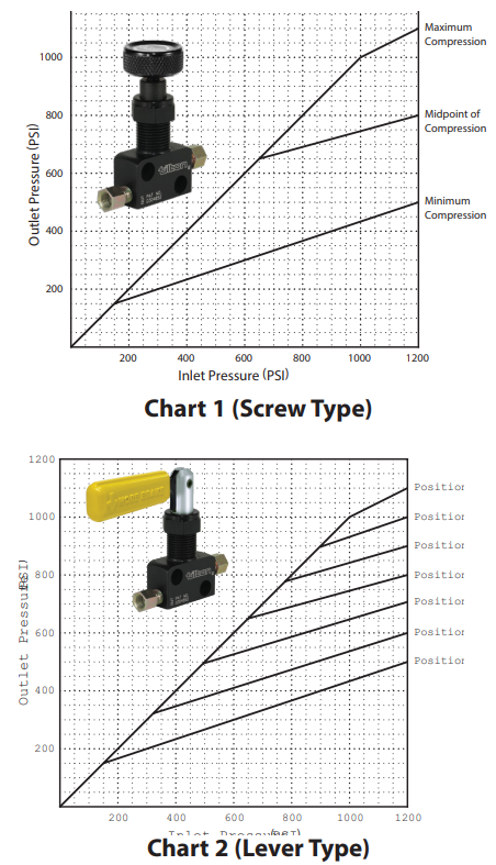
At low pressures the valve behaves like a plain hydraulic connector. Pressure in equals pressure out, a 1:1 ratio, shown by the 45-degree line on the chart. Once line pressure climbs past a set point, the valve switches to a reduced 3:1 rate, so further increases in master cylinder pressure produce a smaller increase at the calliper. The adjustment control simply moves the point where that 1:1 to 3:1 changeover happens.
That dual-slope behaviour is the valve's big advantage over a balance bar on its own. A balance bar gives you one fixed split, say 70 percent front and 30 percent rear, and holds it whether you are braking lightly or standing on the pedal. But axle loading is not fixed. Under heavy braking you want a higher share of braking up front, exactly when load has transferred there. Plumbed into the rear line, the proportioning valve delivers that: light braking stays near the base balance, and heavy braking sends a greater share of the effort to the front callipers.
Where to mount it
Mount the valve on the line feeding the callipers you want to trim, which on almost every setup means the rear. Pick a spot the driver or a crew member can reach easily, since the whole point is being able to adjust it. Two practical rules:
- Leave room for the hydraulic lines and for servicing the valve later.
- Route the lines well clear of heat sources such as exhaust pipes and manifolds.
You can frame-mount it on a bracket or bulkhead-mount it through a panel. The choice usually comes down to where the driver can comfortably reach the knob or lever.
How to install a brake proportioning valve
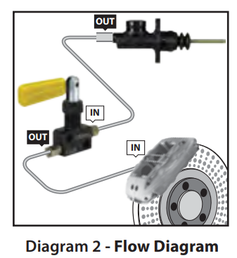
Always connect the master cylinder outlet to the valve inlet, and the valve outlet to the calliper line. Plumbed backwards it will not work.
Frame mounting
- Choose a location that gives easy access to the adjusting handle or knob.
- Confirm there is room for the hydraulic lines and for servicing.
- Mark the two mounting holes against the valve body.
- Drill two 9/32 inch (7 mm) holes and deburr both.
- Test fit, then secure with two 1/4 inch (6 mm) socket head cap screws and locknuts. Screw length depends on your bracket.
- Route the lines carefully, away from exhaust heat.
- Connect master cylinder outlet to valve inlet, and valve outlet to the caliper line.
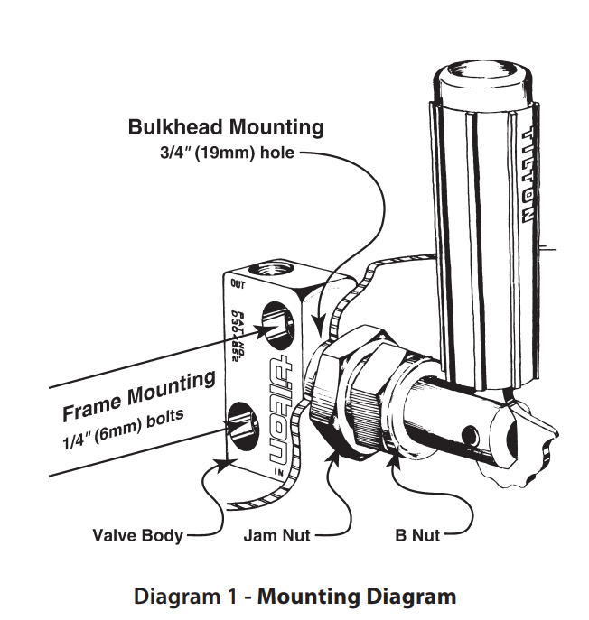
Bulkhead mounting
- Choose an accessible location on the panel.
- Confirm clearance for lines and servicing.
- Mark the single mounting hole.
- Cut, drill or punch a 3/4 inch (19 mm) hole and deburr it.
- Loosen the B-nut and remove the handle assembly from the valve body.
- Loosen and remove the jam nut.
- Slide the valve body through the hole to test fit.
- Refit the jam nut, then reinsert the handle assembly.
- Rotate the handle to the desired position, then tighten the top B-nut to 20 ft-lb with a 7/8 inch wrench. Make sure the B-nut does not touch the jam nut, or the handle may not hold its position.
- Route the lines away from heat.
- Connect master cylinder outlet to valve inlet, and valve outlet to the caliper line.
How to adjust it and set up brake bias
There are two body styles, and the adjustment logic is the same idea on both: more adjustment means less pressure to the rear.
On a proportioning valve screw type fitted to the rear line, turning the knob clockwise allows more pressure to the rear brakes, and counter-clockwise reduces it. On a proportioning valve lever type, pushing the handle toward the front of the car reduces rear pressure and pulling it rearward increases rear pressure. The handle can be re-oriented by loosening the jam nut and rotating it if the action ends up the wrong way around for the driver.
The cleanest way to set it up alongside a balance bar:
- Start with the valve fully open so it is not proportioning yet. Set a screw-type fully clockwise, or a lever-type to Position 7.
- Adjust the balance bar until the rear brakes lock on track with slightly less pedal effort than the fronts.
- Now bring in the valve a little at a time, counter-clockwise on a screw-type or one lever position at a time, until the balance feels right under hard braking.
Which way you trim depends on the discipline. Reducing rear is common for road racing, oval track, trucks and street rods, and helps compensate for fuel burn-off and fading rear grip. Reducing a front is used in dirt, rally and off-road to keep steering bite in loose conditions.
Important notes before you drive
A few things that catch people out:
- Do not use a Tilton-style adjustable proportioning valve with ABS. The high-pressure pulses an ABS system generates will damage the valve seals.
- You cannot bleed the system at high pressure, because above the changeover point a piston separates the inlet and outlet sides and no fluid flows through. Bleed with light pedal pressure, and back the valve fully open first (clockwise on a screw-type, Position 7 on a lever-type) so fluid can pass.
- The valve reduces pressure only. If you need more rear brake than the master cylinder delivers, the valve is not the fix.
Replacing a worn proportioning valve
A valve that no longer holds its setting, leaks, or feels gritty through its travel has usually suffered internal seal wear, often from heat or from being run on an ABS-equipped car. Replacement is a straight swap: note the current position, fit the new valve the same way round (master cylinder to inlet, calliper to outlet), bleed the line, and reset your bias from the fully open starting point above.
Brake proportioning valve FAQs
Where should a brake proportioning valve be installed?
A brake proportioning valve should be installed on the line feeding the callipers you want to trim, almost always the rear, and somewhere the driver or crew can reach the adjuster.
Which way do I turn the knob for more rear brake?
On a rear-line screw-type valve, clockwise increases pressure to the rear and counter-clockwise reduces it.
Can I use a proportioning valve with ABS?
No, ABS pressure pulsations will damage the valve seals. Adjustable proportioning valves are for non-ABS systems.
Is an adjustable valve the same as a factory GM proportioning valve?
No, factory combination or proportioning valves on road cars, including GM units, are set at the factory and are not adjustable. An aftermarket adjustable valve lets you tune bias yourself.
Does a proportioning valve increase brake pressure?
No, it can only reduce pressure to an axle, never add to it.
Standard and metric fittings
Standard valves use an AN-3 port with 3/8 inch-24 threads and ship with AN-3 to AN-3 and AN-3 to 3/16 inch inverted flare fittings. Metric valves use M10 x 1.0 threads with a 74-degree included angle at the base and ship without fittings, so plan your adapters before installation.